Conditional Simulation

Conditional simulation generates multiple equally probable models of grade distribution that honour the input sample data and spatial continuity. Rather than producing a single estimated result, it represents the range of possible geological outcomes, helping users assess uncertainty, risk, and variability in grade control, resource modelling or exploration.
Conditional Simulation Workflow
In Micromine Origin & Beyond, first create a transform file using the Normal Scores Transform tool, creating declustered weights beforehand if required.
Next, create variograms on the grade data, selecting the transform file so the variograms are based on normal scores data.
Then run the Conditional Simulation tool using the grade values for the domain. When the variogram file is selected, the transform file is automatically populated, ensuring the data is transformed for simulation and back-transformed for the final output.
The tool includes aggregating to a larger panel, various summary statistics, and validation via variograms, histograms, and swath plots.
Input and Output
The Input and Output tab of the Conditional Simulation form is used to select the Samples Input and Output files, as well as configure the Simulation Blocks and any Discretisation for the conditional simulation.
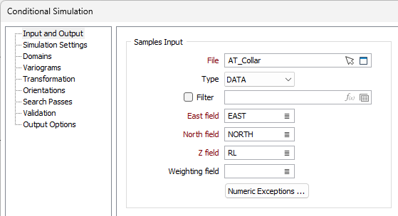
Samples Input
The Samples Input section of the Input tab is used to select the samples for the simulation.
File
Select the file Type and Double click (F3) the File field or use the selection icon to navigate to and select the file containing the sample information. You can also click the Pick from Vizex button to collapse the form and interactively select a layer containing the file to be inserted and return to the form.
Optionally you can set a Filter for the sample file.
East, North and Z
Double-click (F3) to select the names of the fields that contain the North, East and Z coordinates in the sample file.
Weighting Field
Double click (or click the List icon) to select the field in the Sample file which contains sample weight field (To field - From field) information.
Numeric Exceptions
If you click the Numeric Exceptions button, you can control the methods used to process non-numeric values in the file.
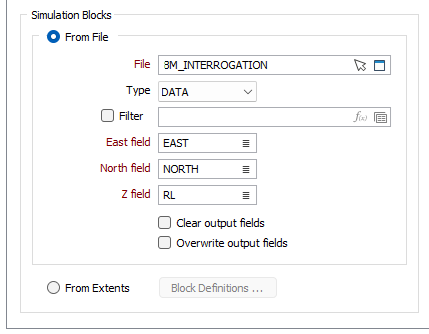
Simulation Blocks
From File
Select this option to define the block model for the simulation from a specified file.
File
Select the file Type and Double click (F3) the File field or use the selection icon to navigate to and select the file containing the sample information. You can also click the Pick from Vizex button to collapse the form and interactively select a layer containing the file to be inserted and return to the form.
Optionally you can set a Filter for the sample file.
East, North and Z
Double-click (F3) to select the names of the fields that contain the North, East and Z coordinates in the sample file.
Clear output fields
Select this option if you want to clear all of the output fields before running the Conditional Simulation to prevent the need to overwrite existing values.
Overwrite output fields
Select this option to overwrite all of the values in the output fields.
From Extents
Select this option to define the block model for the simulation using extents. Click the Block Definitions button to open the Block Model Extents form and define the extents for the simulation blocks.
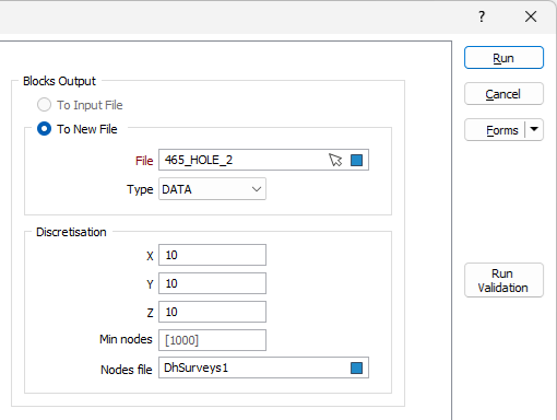
Blocks Output
Where the simulation blocks have been defined from an input file, select To Input File to overwrite the file with the output blocks for the simulation.
If you do not want to overwrite the input file with the simulation data, select the To New File option and specify a new File to write to from the field provided.
File
Select a file Type and double click (F3) or use the Select icon in the File field to navigate to a location and name the output for the blocks output. If you select an existing file, you will be asked to overwrite or append it when the simulation is run. You can also click the Pick from Vizex button to collapse the form and interactively select a layer containing the file to be inserted and return to the form.
Discretisation
The fields in the Discretisation section of the form are used to specify the number of divisions in each direction for the interpolation.
X, Y, Z
Specify the number of divisions in the X, Y, and Z directions. These are integer values that control the number of discrete points to be queried in each direction within each block. The values of all the discretised points are then averaged to estimate a single value for the block, which is written to the output file. See Discretisation.
Min nodes
The minimum number of nodes for discretisation is automatically calculated from the X, Y and Z values and is displayed as the default value in the Min nodes field. You can enter a custom minimum value if required.
Nodes file
Double click (F3) or use the folder icon in the Nodes file field to select the nodes file for the discretisation. A specified Nodes file can be used for Variography validation - see Validation.