

What’s New
This
 Nexus Integration
In the Project Explorer, when you right-click on the root node you can now select an option to integrate your Micromine Spry projects with Nexus.

Micromine Nexus is a web-based, enterprise-level file management solution which seamlessly integrates with Micromine applications and Open API applications to provide secure data storage, file versioning and access control, plus flexible tools to facilitate the governance of corporate-wide business processes.
For more information, see: Nexus Integration
Micromine Cloud Licensing
When you click the File tab to open the Backstage menu and select Licensing, you can now click Change Licence to choose between Micromine Cloud Licensing Services (MCLS) and Legacy Cloud Licensing Services:
A Micromine Cloud Licence is a network-style licence hosted in the cloud on Nexus. Micromine Nexus is a web-based, enterprise-level file management solution which seamlessly integrates with Micromine applications and Open API applications to provide secure data storage, file versioning and access control, plus flexible tools to facilitate the governance of corporate-wide business processes.
To configure a licence from the Micromine Cloud Licensing Service (MCLS):
-
(A) If a valid legacy or Micromine licence is NOT detected, when the application starts, a Licensing splash screen will display an error message indicating that a licence has either not been found or is not valid.
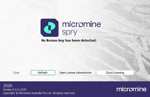
Click the Cloud Licensing button. See Step 2.
-
(B). Alternatively, if a valid Legacy or Micromine licence has been detected and the application is already open, click File to open the Backstage menu and select Licensing > Change Licence.
-
In the Licence Options dialog, select Micromine from the Licensing System drop-down.
To view and access available cloud licences for Spry, you must sign in with your Micromine ID. If you are not Signed in, click the Sign In button to sign in to Nexus. For further information on signing in, see: Nexus Home
Once signed-in, if cloud licences are available and you have the necessary permissions, you can manage those licences. (If there are no cloud licences available you will need to request one from your licence administrator.)
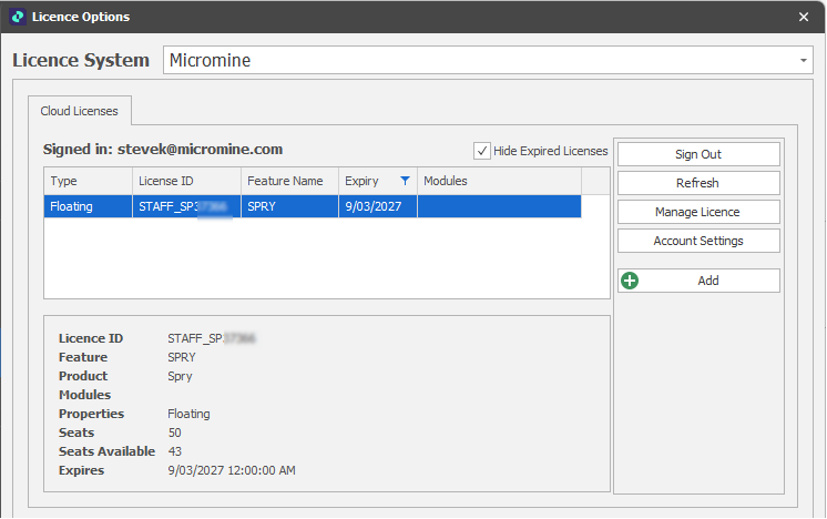
By default, expired licences are not shown in the grid and the Hide expired licences is selected. Deselect this check box if you want to see expired licences.
-
Click in the grid to select a licence and then click the Add button to add the selected licence to the Licence Configuration pane in the lower half of the Cloud Licences tab.
There may be a pool of licences and modules that you are able to choose from when working in the application. Each combination of licence and modules is known as a configuration.
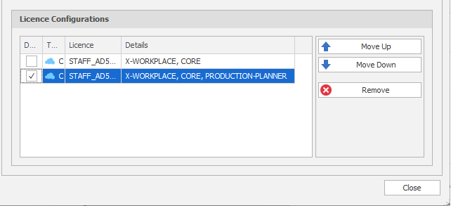
If you want the application to automatically activate a particular licence configuration when it starts up, select the Default check box next to the name of that configuration:
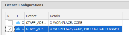
Optionally, click the Move Up and Move Down arrows to adjust the order of the licence configurations.
If your current licence is no longer available or is no longer valid, this is the order of precedence the application will use when attempting to activate an alternative licence.
-
If not already selected, click to Select the licence you want to activate in order to use the application (this will typically, be your "Default" licence) and then click Close to close the Licence Options dialog.
-
(A) If a valid legacy or Micromine licence was NOT previously active, see Step 1 (A), click the Refresh button .
If the chosen licence is valid, the licence is checked-out and the application will start-up.
(B) Alternatively, if a valid legacy or Micromine licence was previously active and the application is currently open, see Step 1 (B), you will be prompted to restart the application in order for the licensing changes you have made to be applied.
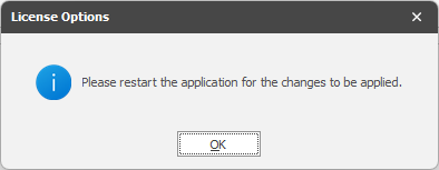
Click OK and Restart the application.
Once your licence is active, you can do the following:
Manage Licence
Click Manage Licences to open the Nexus Home - Manage Licences page.

This option is also available on the Backstage > Licensing page when a Micromine cloud licence is active.
Account Settings
Click Account Settings to open the Nexus Home - User Profile page.
For information on the technical requirements for Cloud Licensing, see: Technical Requirements
For answers to a number of frequently asked questions, see: Cloud Licensing: FAQs
For more information, see: Licensing Options
Automatic Road Tool
Add Parametric Steps
On the Shape tab, in the Add group, when you define a set of parametric line segments to create a road, in addition to adding Straight and Curve step types, you can now select Auto and Multiple step types.
These are composite steps which are converted to their component steps (straights and curves) when added to a road.
Auto
From a chosen start point (or the current “final point”) and a chosen end point, user-defined Radius and Grade values are used to Auto compute a set of segments which progress from the designated start point towards the end point.
Multiple
The Multiple step type applies a repeated vector to created multiple auto connections between recurring points. The loop vector and direction is flipped between each point to create the desired figure eight shape.
You can choose between a Helix or Figure Eight auto loop type:
|
Helix |
Uses the current point/direction and requires an end point/direction. One of four possible Helix options is chosen to connect the two points. Which option is chosen is determined by a fifth option which checks all of the roads and finds the shortest. The number of loops and where the loops are placed along the path to a second point is determined by the Grade and Radius values specified. |
|
Figure Eight |
Uses the current point/direction and requires an end point and a loop direction. The loop is always placed along the mid point between the start and end point. A shortest path is used to connect the mid loop with the start point. The size of the loop tangents are determined by the Grade and Radius values specified. The loop direction can be clockwise or counter clockwise. |
Delete
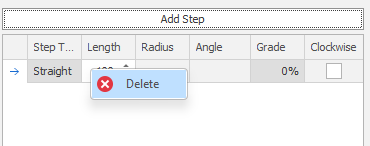
When you add parametric steps, you can now right-click to Delete the selected step.
Design Window
Sectional View
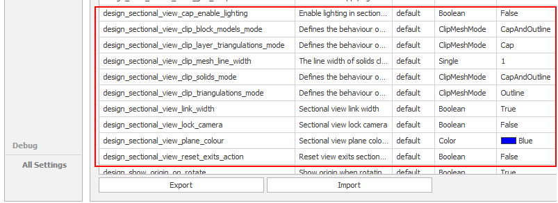
On the Design tab, in the Action group, when you select Create Sectional View to create a sectional view from the current plan view, you can now specify an Outline Width and also select a different Clip Mesh Mode for Layer Triangulations, Triangulations and Block Models.
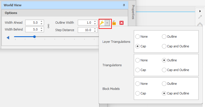
You can set defaults for the same settings via Tools > Settings > All Settings:
Snap Limits
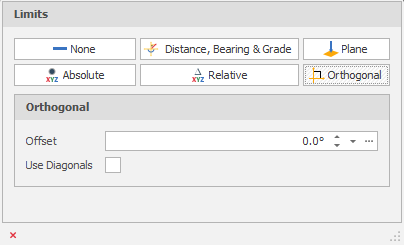
On the Design tab, in the Snap group, in the Limits drop-down pane, you can now select an Orthogonal option to limit the snap operation to a point which is orthogonal to another point when drawing lines.
Straight lines can be drawn at angles {0°,90°,180°,270°} with a specified offset. When the Include diagonals check box is selected, a new limit option is available every 45° instead of every 90°, e.g {0°,45°,90°,135°,180°,225°,270°,315°}.
Navigation Cube Shortcuts
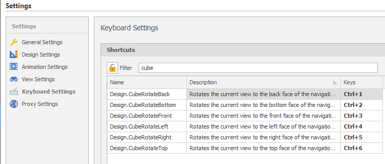
In Settings > Keyboard Settings, you can now assign shortcuts to rotate along the Navigation Cube main faces in the Design Window. In this example, the commands have been bound to CTRL + <number-key> combinations:
Export to PDF
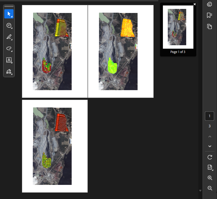
When you right-click in the Design Data pane and select Export | PDF, in addition to exporting layers, it is now possible to export the georeferenced images that can be combined with those layers to assist in visualisation.
Export Design Data to PDF: Output
Animation Element Visibility
In the Animation Window, Block Model, Grid, Triangulation and Text elements can now be added to Haulage Network layers alongside Haulage Network Shapes. These elements can all be shown or hidden at certain dates in the schedule.
-
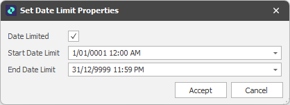
Right-click on the Shape, Grid, Triangulation or Block Model layer and select Set Date Limit Properties:
-
Select the Date Limited check box to enable the (StartDateLimit, EndDateLimit) element visibility properties you have set.
-
Click Accept.
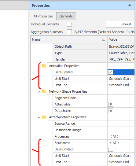
The same properties can be enabled and adjusted in the Design Properties pane:
Triangulation Utilities
Project Boundary to Plane
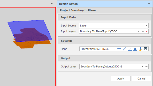
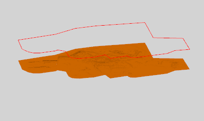
On the Triangulation tab, in the Utility group, you can now create silhouette outlines of selected triangulations using a plane's normal and then project them onto that plane. (CTRL+P,B)

Split by Multiple Planes
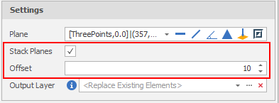
On the Triangulation tab, in the Split/Merge group, when you select Clip by Plane to clip one or more triangulations where they fall above or below a user-defined plane, you can now select an option to stack multiple planes by specifying an offset value:
Shapes
Fillet Corners by Angle
On the Shape tab, in the Utility group, you can select an option to detect sharp corners and apply radial or straight fillets.

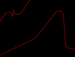
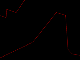
You can choose whether to fillet all corners or only fillet sharp corners less than a specified maximum angle and chooose between a Curved (each corner is rounded) or Straight (each corner is cut off) fillet mode.
|
Curved: |
|
|
Straight: |
|
Split Shapes by Interpolation
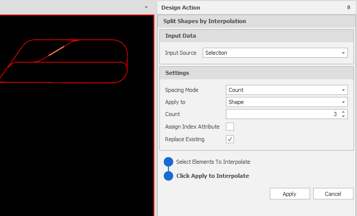
On the Shape tab, in the Add group, you can now select Split Shapes by Interpolation to insert points on one or more selected shapes or the selected segment of a shape and split those shapes (or the segment) accordingly. (Ctrl + S, I)
For example, if a segment is 200 metres long and 2 points are inserted (one a distance of 90 metres and a second at a distance of 180 metres) three segments will be created (two segments 90 metres in length and one segment 20 metres in length).

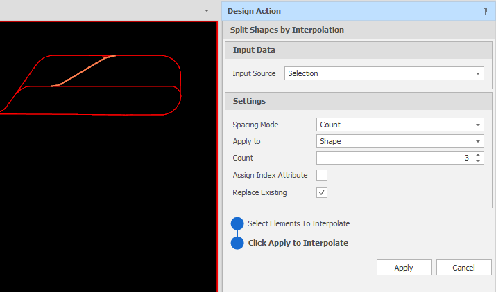
In this example, the selected shape is split based on the segment Count value entered:
Insert Points by Interpolation
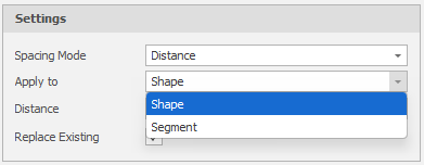
On the Shape tab, in the Add group, when you click Insert Points by Interpolation to insert points, you can now choose an Apply To mode to interpolate points on one or more selected shapes or insert points on the selected segment of a single shape:
Create Circle
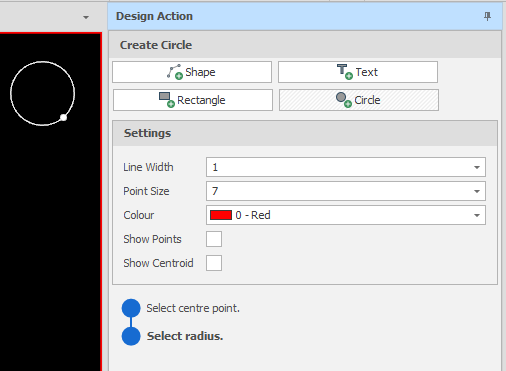
On the Shape tab, in the Add group, you can now select Create Circle to add one or more circles to the Design Window. An active (non-Network) layer must be selected. (Ctrl+D,C)

Click to select a Centre Point and then drag the mouse and click to set the Radius. A circle is rubber-banded in the direction you move the mouse cursor and is drawn in the current plane of the camera.
Block Model Exports
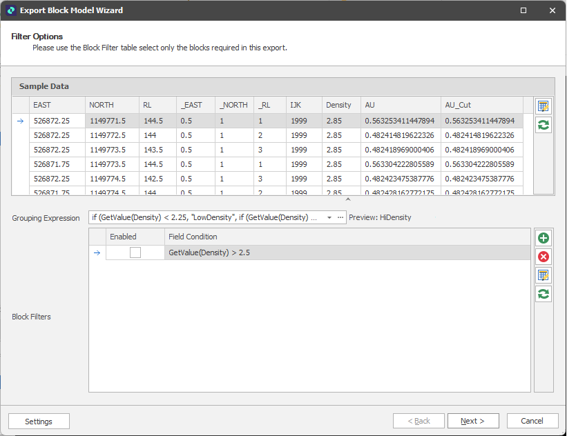
In the Design Data pane, you can now right-click on a block model layer and select an option from the Export menu to export your block model to an (.xml) Properties file, to a Micromine (.dat) block model file, or to a Comma Separated Value (*.csv) file.
When exporting to a Micromine (.dat) or Comma Separated Value (*.csv) file format, a reduced or transformed copy of the underlying block model file can be exported and optionally re-imported. Overall file size can be reduced by applying one or more filter conditions. You can also use a grouping expression to split the block model into smaller separate files based on the values of the fields in the block model file.
Block Model Export Wizard
Table Data
Table Parameters
In the Expression Editor, Table Parameter functions have now been extended to allow data type-specific (Boolean, Float and Integer) values to be returned in addition to Text and Date. A new RowIndex function also returns the index of the matched row.
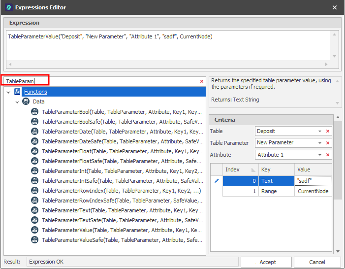
Expression Editor: Table Parameters
Import/Export
When you right-click on a table, you can now export and import solids in Datamine (.dmx, .dm) file format:
-
To import solids from a Datamine (.dm, .dmx) file: In the Project Explorer, right-click on a Table and select Import > Solids > From Datamine Objects.
-
To export table solids to Datamine binary (*.dm, *.dmx) file format: In the Project Explorer, right-click on a Table and select Export > Data to Datamine Files.
Layer Imports/Exports (Datamine)
In the Design Data pane, Shape and Triangulation layers can now be exported/imported in Datamine file format:
-
To export a Shape layer to a Datamine (.DMX, .DM) file: In the Design Data pane, right-click on the Layers node or the name of a layer and select Export > Shapes to Datamine String.
-
To export a Triangulation layer to a Datamine (.DMX, .DM) file: In the Design Data pane, right-click on the Layers node or the name of a layer and select Export > Triangulations to Datamine Wireframe.
-
To import design data from a Datamine (.dm, .dmx) file: In the Design Data pane, right-click on the Layers node or the name of a layer and select Import > Datamine Files.