

Create Road

The same option is available when you right-click on a designated start point in the design window.
A road connects access points between pits, dumps and stockpiles.
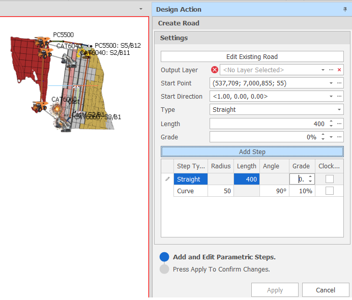
Create Road Design Action
 Edit Existing Road
-
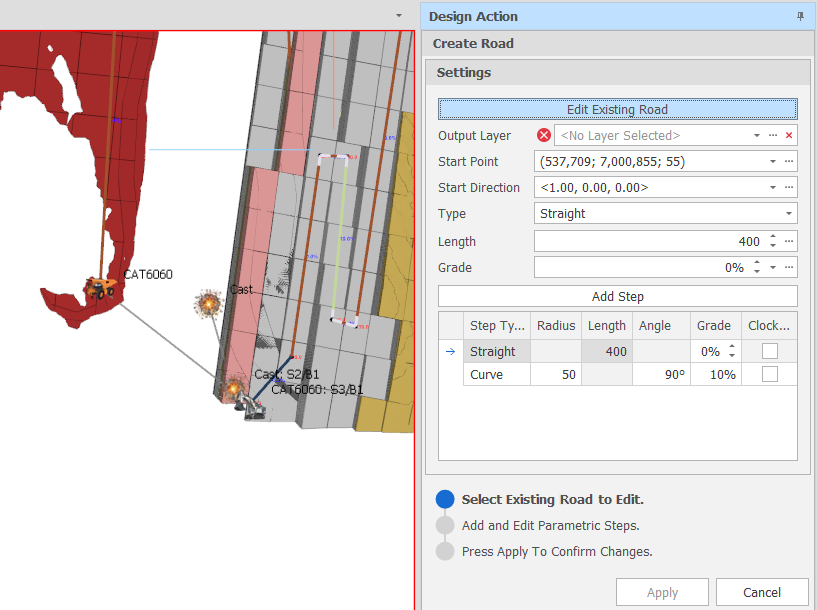
Click the Edit Existing Road button if you want to edit a road you have previously created and saved. The road must already be loaded in the display.
You will be prompted to select the road you want to edit:
-
When you click to select the road, the saved settings of the road are loaded and previewed in the display:
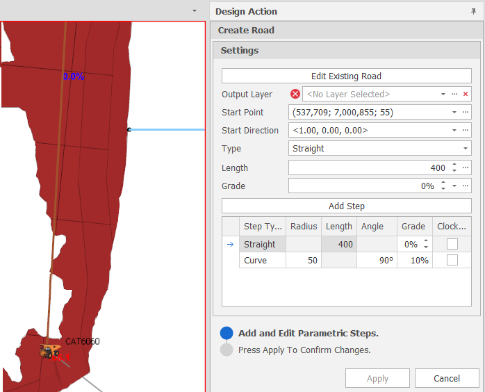
You can continue to Add and Edit Parametric Steps (see below).
Add and Edit Parametric Steps
You can add and edit the parametric steps of an existing road or add and edit parametric steps to create a road from scratch.
If you are editing an existing road (see above) the saved settings of the road are loaded and previewed in the display. If you are creating a road from scratch, segment settings previously specified in the current session (if any) are loaded and previewed in the display.
To create or edit a road, specify the following Settings:
Output Layer
If you are creating a layer from scratch, use the drop-down to select an Output Layer. The segments you add to the display will be written to this layer.
Tip: You can right-click on a folder in the Layer Selection pane to Add a new layer.
Start Point
Click the ellipsis to digitise a Start Point in the Design Window. An initial segment is projected in the direction of the default Start Direction (see below).
Alternatively, use the drop-down to enter the coordinates of a known point (or adjust the coordinates of the point you have digitised).
Start Direction
Click the ellipsis to set the Bearing and the Slope of the initial segment by digitising a point.
Alternatively, use the drop-down to select a Bearing and a Slope that defines the vector.
Type
Click the drop-down to set the (Straight, Curve, Auto or Multiple) Step Type. Auto and Multiple are composite steps which are converted to their component steps (straights and curves).
Any other settings you need to specify will differ, depending on the Type you have chosen:
Curve
Radius
The radius of the circle the curve is moving around.
Angle
The angle of the circle to add (90° adds a quarter of a circle for example, 180° adds a half circle). See Add Quarter and Add Half below.
Grade
Click the ellipsis to set the Line Grade or Z angle between the end points of the segment by digitising a point in the Design Window.
Alternatively, enter (or use the drop-down to select) a Grade percent value.
Clockwise
Select this check box if the curve moves clockwise around the specified circle (i.e. turns left or right). Movement is counter clockwise when the check box is not selected.
Add Quarter
Click the Add Quarter button to add a quarter circle (Angle = 90° but otherwise based on the curve properties you have specified).
Add Half
Click the Add Half button to add a half circle (Angle = 180° but otherwise based on the curve properties you have specified).
Add Step
Click Add Step to add a segment based on the Curve settings you have specified. Clicking Add Step after clicking Add Quarter or Add Half, will repeat the Add Quarter or Add Half step.
Straight
Length
Click the ellipsis to set the length of the segment by digitising a point in the Design Window.
Alternatively, enter (or use the drop-down to select) a Length value.
Grade
Click the ellipsis to set the Line Grade or Z angle between the end points of the segment by digitising a point in the Design Window.
Alternatively, enter (or use the drop-down to select) a Grade percent value.
Add Step
Click Add Step to add a segment based on the Straight line settings you have specified.
Auto
From a chosen start point (or the current “final point”) and a chosen end point, user-defined Radius and Grade values are used to Auto compute a set of segments which progress from the designated start point towards the end point.
Settings
The settings you need to specify will differ, depending on the Loop Type you have selected:
Loop Type
You can choose between a Helix or Figure Eight auto loop type:
|
Helix |
Uses the current point/direction and requires an end point/direction. One of four possible Helix options is chosen to connect the two points. Which option is chosen is determined by a fifth option which checks all of the roads and finds the shortest. The number of loops and where the loops are placed along the path to a second point is determined by the Grade and Radius values specified. |
|
Figure Eight |
Uses the current point/direction and requires an end point and a loop direction. The loop is always placed along the mid point between the start and end point. A shortest path is used to connect the mid loop with the start point. The size of the loop tangents are determined by the Grade and Radius values specified. The loop direction can be clockwise or counter clockwise. |
| Settings | Loop Type = Figure Eight |
|---|---|
End Point |
Click the ellipsis to digitise an End Point in the Design Window. Alternatively, use the drop-down to enter the coordinates of a known point (or adjust the coordinates of the point you have digitised). |
Loop Direction |
Click the ellipsis to set the Bearing and the Slope of the loop. Alternatively, use the drop-down to select a Bearing and a Slope that defines the vector. |
Radius |
The radius of the circle the Curve Segment is moving around. |
Grade |
Click the ellipsis to set the Line Grade or Z angle between the end points of the segment by digitising a point in the Design Window. Alternatively, enter (or use the drop-down to select) a Grade percent value. |
Clockwise |
Select this check box if the curve moves clockwise around the specified circle (i.e. turns left or right). Movement is counter clockwise when the check box is not selected. |
Repeat Count |
Specify the number of times that the auto step will be repeated. |
| Settings | Loop Type = Helix |
|---|---|
End Point |
Click the ellipsis to digitise an End Point in the Design Window. Alternatively, use the drop-down to enter the coordinates of a known point (or adjust the coordinates of the point you have digitised). |
End Direction |
Click the ellipsis to set the Bearing and the Slope of the End Segment by digitising a point. Alternatively, use the drop-down to select a Bearing and a Slope that defines the vector. |
Radius |
The radius of the circle the Curve Segment is moving around. |
Grade |
Click the ellipsis to set the Line Grade or Z angle between the end points of the segment by digitising a point in the Design Window. Alternatively, enter (or use the drop-down to select) a Grade percent value. |
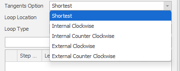
Tangent Options |
Choose how the tangents between curved and straight segments will be calculated and drawn.
|
Loop Location |
Set the (Start, End, Incremented Start, Incremented End) location of the loops that will be generated along the path to the second point. |
Add Step
Click Add Step to add a segment based on the Straight line settings you have specified.
Multiple
The Multiple step type applies a repeated vector to created multiple auto connections between recurring points. The loop vector and direction is flipped between each point to create the desired figure eight shape.
Input Data
When the step type is Multiple and the Mode setting (see below) is Existing Line, a layer must either be specified as the input layer or be loaded as the active layer.
| Selection | Design elements you have interactively selected in the Design Window. |
| Visible | Design elements that are visible in the loaded layer. Elements that have been specifically hidden are excluded. This a quick way of selecting all visible elements in a layer without having to explicitly select them. |
| Layer | One or more layers that you select. Names of layers currently loaded in the Design Window are shown in bold. |
Settings
Mode
Choose between an Existing Line or Repeated mode of operation.
|
Existing Line |
Auto steps will be generated along one or more existing lines. ... See Input Data. |
|
Repeated |
Auto steps will be generated repeatedly along the path towards a specified End Point . |
The settings you need to specify will differ, depending on the Mode and the Loop Type you have selected:
Loop Type
You can choose between a Helix or Figure Eight auto loop type:
|
Helix |
Uses the current point/direction and requires an end point/direction. One of four possible Helix options is chosen to connect the two points. Which option is chosen is determined by a fifth option which checks all of the roads and finds the shortest. The number of loops and where the loops are placed along the path to a second point is determined by the Grade and Radius values specified. |
|
Figure Eight |
Uses the current point/direction and requires an end point and a loop direction. The loop is always placed along the mid point between the start and end point. A shortest path is used to connect the mid loop with the start point. The size of the loop tangents are determined by the Grade and Radius values specified. The loop direction can be clockwise or counter clockwise. |
| Settings | Mode = Existing Line, Loop Type = Figure Eight |
|---|---|
Loop Direction |
Click the ellipsis to set the Bearing and the Slope of the loop. Alternatively, use the drop-down to select a Bearing and a Slope that defines the vector. |
Radius |
The radius of the circle the Curve Segment is moving around. |
Grade |
Click the ellipsis to set the Line Grade or Z angle between the end points of the segment by digitising a point in the Design Window. Alternatively, enter (or use the drop-down to select) a Grade percent value. |
Clockwise |
Select this check box if the curve moves clockwise around the specified circle (i.e. turns left or right). Movement is counter clockwise when the check box is not selected. |
| Settings | Mode = Existing Line, Loop Type = Helix |
|---|---|
End Direction |
Click the ellipsis to set the Bearing and the Slope of the End Segment by digitising a point. Alternatively, use the drop-down to select a Bearing and a Slope that defines the vector. |
Radius |
The radius of the circle the Curve Segment is moving around. |
Grade |
Click the ellipsis to set the Line Grade or Z angle between the end points of the segment by digitising a point in the Design Window. Alternatively, enter (or use the drop-down to select) a Grade percent value. |
Tangent Options |
Choose how the tangents between curved and straight segments will be calculated and drawn.
|
Loop Location |
Set the (Start, End, Incremented Start, Incremented End) location of the loops that will be generated along the path to the second point. |
| Settings | Mode = Repeated, Loop Type = Figure Eight |
|---|---|
End Point |
Click the ellipsis to digitise an End Point in the Design Window. Alternatively, use the drop-down to enter the coordinates of a known point (or adjust the coordinates of the point you have digitised). |
Loop Direction |
Click the ellipsis to set the Bearing and the Slope of the loop. Alternatively, use the drop-down to select a Bearing and a Slope that defines the vector. |
Radius |
The radius of the circle the Curve Segment is moving around. |
Grade |
Click the ellipsis to set the Line Grade or Z angle between the end points of the segment by digitising a point in the Design Window. Alternatively, enter (or use the drop-down to select) a Grade percent value. |
Clockwise |
Select this check box if the curve moves clockwise around the specified circle (i.e. turns left or right). Movement is counter clockwise when the check box is not selected. |
Repeat Count |
Specify the number of times that the auto step will be repeated. |
| Settings | Mode = Repeated, Loop Type = Helix |
|---|---|
End Point |
Click the ellipsis to digitise an End Point in the Design Window. Alternatively, use the drop-down to enter the coordinates of a known point (or adjust the coordinates of the point you have digitised). |
Radius |
The radius of the circle the Curve Segment is moving around. |
Grade |
Click the ellipsis to set the Line Grade or Z angle between the end points of the segment by digitising a point in the Design Window. Alternatively, enter (or use the drop-down to select) a Grade percent value. |
Tangent Options |
Choose how the tangents between curved and straight segments will be calculated and drawn.
|
Loop Location |
Set the (Start, End, Incremented Start, Incremented End) location of the loops that will be generated along the path to the second point. |
Repeat Count |
Specify the number of times that the auto step will be repeated. |
Add Step
Click Add Step to add a segment based on the Straight line settings you have specified.
Preview Colours
The following colours are applied to the Straight line and Curves in the display, both prior to and after adding them as steps:
|
Colour |
Usage |
|---|---|
|
White |
The last added step. |
|
Orange |
The current step that will be added if Add Step is clicked. |
|
Blue |
The step selected in the Steps grid (defaults to the first step when an existing layer is loaded). |
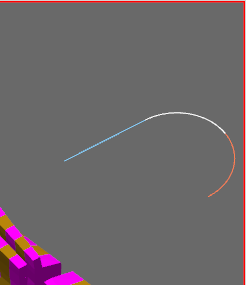
Preview Colours
Modify Steps
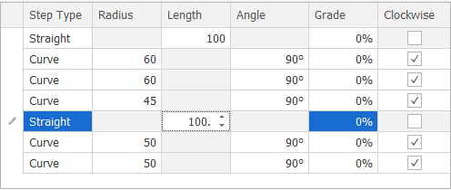
In the Steps grid, modify the parameters of a step by selecting a grid row. The Straight line segment or Curve you have selected is highlighted in the Design Window. Any changes you make to the settings of the Straight line segment or Curve are immediately reflected in the design.
Delete
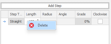
When you add parametric steps, you can right-click to Delete the selected step.
Apply
Finally. click Apply to save the Steps and the Settings you have specified.