

Guides

The Generate Guides tool automatically generates contours from a specified wireframe or block model and creates editable user type constraints on the current active pit design.
Generated constraints are saved in the pit design file are tagged with the specified wireframe type and name or block model name. This tag is updated when you edit the constraint.
Repeating the tool process with the same guides will overwrite all unedited constraints generated previously (if present) to avoid producing copied or ambiguous constraints.
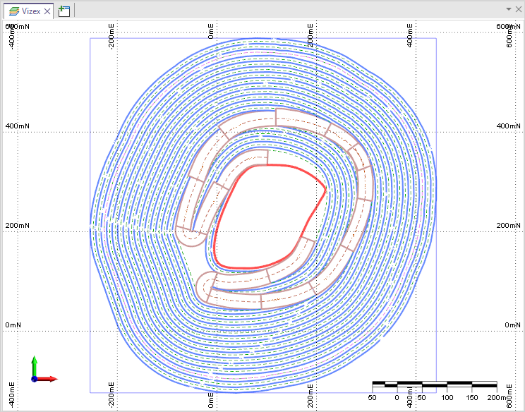
In the Generate Guides form, you can select whether to generate the guides from a Guides Wireframe or Block Model.
Guides Wireframe
Select this option to specify a wireframe to use in generating guides for the pit design.
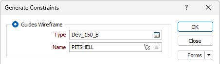
Type, Name
Use the Type and Name fields to specify select wireframe type and the name of a wireframe of that type to use to generate guides for the pit design.
You can also use the Pick from Vizex button (or select the context menu option where available) to collapse the form and interactively select the required Wireframe to insert and return to the form.
Block Model
Select this option to specify a block model to be used in generating guides for the pit design.
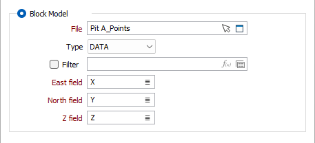
File
Double-click (or click on the Select icon) to select the name of the Block Model (*.DAT) file to be used to generate guides. You can also click the Pick from Vizex button to collapse the form and interactively select a layer containing the file to be inserted and return to the form.
Optionally, select or create a filter to limit the data that is processed.
Easting, Northing and Z fields
Specify Easting, Northing and Z coordinate fields for the block model file.
Polygon Smoothing
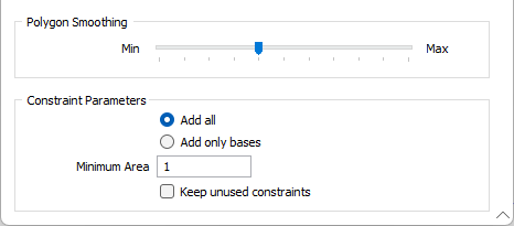
Use the Polygon Smoothing slider to specify the level of smoothing to be applied to the polygons for the guides.
The higher the value, the closer the shape of the generated guide string will be to the original. On a sliding scale of 1 to 10, a value between 7 - 9 usually gives the best result.
When the slider is set to 0.0, no smoothing is applied to the constraints, and the result is generated without any smoothing.
Constraint Parameters
Select whether to Add only bases or Add all constraints generated by the tool to the pit design.
For pit designs with no bases defined, top/bottom contours will be assumed as bases to start off a pit.
Minimum Area
Enter the Minimum Area for the generated constraints. Any constraints which do not meet the specified area requirement will not be added. You can also accept the default value of 0 which results in no minimum area.
Keep unused constraints
Select the Keep unused constraints option to retain incoming constraints even when evaluated as having no effect on the pit.
This option is not selected by default. Leaving it OFF will mean constraints with no effect on the design will not be added.
Forms
Click the Forms button to select and open a saved form set, or if a form set has been loaded, save the current form set.
OK
When you have set input and output parameters and optionally applied a polygonal restriction, click OK to begin the process.