Generate From Pit Shells

The Create from Pit Shells tool allows you to specify a block model and output a new pit design, pre-populated with the extracted data:
-
The block model is used to create the guides wireframe;
-
The Guides wireframe can be used to create the bench list (using extents and default bench height) and constraints;
-
Smoothing can be applied to polygons for the design;
-
Constraints can be used to build the approximated pit;
-
An optional Stage field can be used to output the design in various stages.
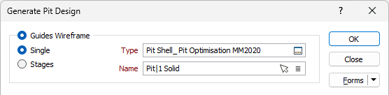
Guides Wireframe
Select the Guides Wireframe option to create the new dynamic pit design from a specified Single or Staged Wireframe Type and Name.
Single / Stages
Select whether to create the pit design for a single guides wireframe or from a wireframe to be used as separate stages.
Type
Double click (F3) in the Type field to select the wireframe to be used for creating the new pit design.
Name
If you selected the Single option, use the Name field to select the wireframe name from the specified wireframe type. You can also use the Pick from Vizex button (or select the context menu option where available) to collapse the form and interactively select the required Wireframe to insert and return to the form.
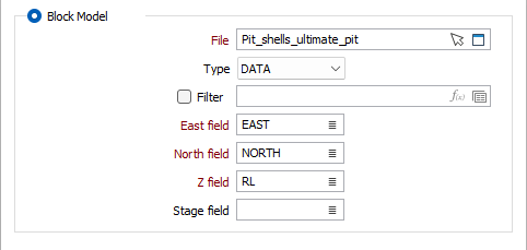
Block Model
Select the Block Model option to specify the details of the block model to be used in creating the new dynamic pit design.
File
Enter (or double-click to select) the Block Model file. The default file Type for Block model data is DAT. You can also click the Pick from Vizex button to collapse the form and interactively select a layer containing the file to be inserted and return to the form.
Optionally, select or create a Filter to limit the data that is processed.
Easting, Northing, Z
Specify the names of the X, Y and Z coordinate fields in the Block Model file.
Stage field
(Optionally) Double click (F3) or use the list icon to select the field in the Block Model used to build Stages in the pit design.
Pit Design Settings
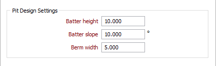
The Pit Design Settings options are used to specify the batter and berm values for the new pit design.
Batter height
Enter the batter height for the pit design (in grid units).
Batter slope
Enter the default angle, measured from the horizontal, between successive toe and crest strings for the new pit design. For block model inputs, the default Batter Slope value is 72.
Berm width
Enter the horizontal distance in grid units between a toe and a corresponding crest at the same level.
For detailed information on the Pit Settings parameters described here, see Setup.
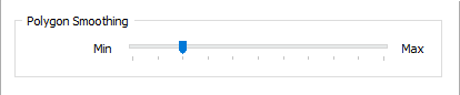
Polygon Smoothing
The Polygon Smoothing slider is used to specify the level of smoothing to be applied to the polygons for the design to be created.
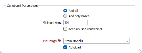
Constraint Parameters
The Constraint Parameters options are used to configure the minimum area for the new pit design, as well as specify whether to add any unused constraints.
Add all / Add only bases
Select whether to create a pit design including the base and All of the generated benches from the input file, or Only Bases for the design.
Minimum Area
Enter a Minimum Area for the created pit design in the field provided. The default value is 0, indicating the pit design is valid regardless of the total area.
Keep unused constraints
Select the Keep unused constraints option to retain incoming constraints even when evaluated as having no effect on the pit.
This option is not selected by default. Leaving it OFF will mean constraints with no effect on the design will not be added to the pit design output.
Pit Design file
Specify a name for the output Pit Design file. If you select an existing design, you will be prompted to overwrite it.
Autoload
Select the Autoload option to load the generated output in Vizex.