

Bench List

Defaults
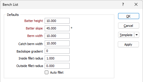
Batter height
After the initial cut the Bench will present a face, and at this stage a bench can also be called a Batter.
Batter height is the vertical distance between Toe and Crest of the bench or the vertical distance between the upper surface of the bench and the lower (floor) surface of the bench. It is the Batters that form the final pit limits.
A "bench', on the other hand, is an operational open-pit concept. Pits are mined by benches, this is the unit of reference for extraction. A bench has an upper and lower surface. It can be described as a tabular body with a specific thickness called Bench Height. When benches achieve the final pit limit they form a pit 'batter'.
Berm Type
The berm type for the bench - Default, Catch, Custom or None. The Berm type can be viewed and edited in the Data Properties for the bench.
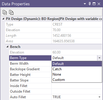
The Custom berm type allows you to change the Berm Width for the berm from the default value to a custom solid value. Changing the Width of a berm will automatically set the Berm Type to Custom.
If no value is set for Width, then the Berm Type will be Default and the default width will apply. Setting the Berm Type to Default or Catch will change the width to the default value.
Berm width
The Berm width is the horizontal distance between a toe and a corresponding crest at the same level.
Berm Width is used to define the required width between bench faces. It is the measurement from the toe of the upper bench to the Crest of the lower Bench. Berms are necessary to provide slope stability and other safety reasons.
Catch Berm Width
Enter the width of the default width of the catch berms throughout the design.
Ramp Gradient Unit
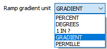
The ramp gradient unit is the unit of measurement for the gradients of elements such as roads, ramps, switchbacks in your design. Use the drop down list to select the default Ramp Gradient unit:
Backslope Gradient
Sometimes a slope may need to be designed into the berms in order to collect water or stone fragments against the pit wall.
Enter a Backslope Gradient value. The value you enter should fall between 1% and 30% (typically 5 or 10) %.
If your configured gradient unit is not percent, the value you enter will be capped to the values converted into those units that are equal to 1%-30%.
The Backslope Gradient value can be modified in the Data Properties for the bench.
Batter slope
The Batter slope is the default angle, measured from the horizontal, between successive toe and crest strings. The angle is measured in degrees to 2 decimal places and the angle value should be greater than 0 and less than 90.
Inside fillet radius
Optionally enter an Inside fillet radius to condition the resultant pit strings. Fillets are applied to angles on the pit strings which range from acute to obtuse. The Inside fillet radius value applies filleting to angles on the inside of the string perimeters.
Outside fillet radius
Optionally enter an Outside fillet radius to condition the resultant pit strings. Fillets are applied to angles on the pit strings which range from acute to obtuse. The Outside fillet radius value applies filleting to angles on the outside of the string perimeters.
Minimum Area
Enter the minimum base area that a bench must have before it is created. Setting a minimum area value can prevent some small benches being generated in areas which are virtually flat.
The default Minimum Area value is calculated by the application as 9x the default Berm width squared.
Interramp angle
The Interramp angle is the slope angle produced by a number of benches. The value in the field is automatically calculated from the Batter Slope, Batter Height and Berm Width values, which are assumed to be constant.
The overall slope angle, on the other hand, is the angle of a line from the toe at the bottom of the pit, to the crest of the pit surface. Since this slope takes into account the haul roads and all working levels, it will not be constant at all parts of the pit.
It therefore follows that the Interramp angle will be steeper than the overall slope angle, and this must be taken into consideration during the pit design.
Auto fillet
The Auto fillet option
For the Bench List, selecting the Auto fillet option will select Auto fillet in the Bench List grid for every bench. You can deselect the option in the Bench List grid for any bench to which auto fillet should not apply.
Benches
The Bench Levels grid displays a list of the benches in the current pit design.
Bench Levels Grid
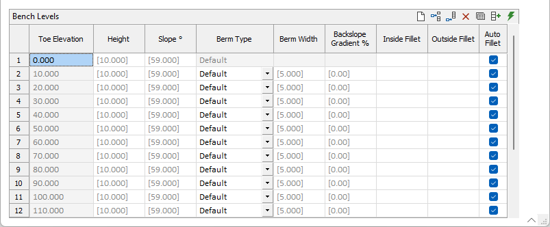
The Bench Levels grid contains the following values for each bench in the list :
|
Toe Elevation |
The elevation of the inside peak formed by the intersection of the bench face and bench floor. |
|
Height |
The height in grid units for the bench. The Batter Height value can be viewed and modified in the Data Properties pane. |
|
Slope ° |
The degree value of the slope for the bench. The default is 45°. The Batter Slope value can be viewed and modified in the Data Properties pane. |
|
Berm Type |
The berm type for the bench - Default, Catch, Custom or None. The Berm type can be viewed and edited in the Data Properties for the bench.
The Custom berm type allows you to change the Width for the berm from the default value to a custom solid value. Changing the Width of a berm will automatically set the Berm Type to Custom. If no value is set for Width, then the Berm Type will be Default and the default width will apply. Setting the Berm Type to Default or Catch will change the width to the default value. |
|
Berm Width |
The width in grid units of the selected berm type for the bench. The default value is 10. Berm Width is used to define the required width between bench faces. It is the measurement from the toe of the upper bench to the Crest of the lower Bench. Berms are necessary to provide slope stability and other safety reasons. The Berm Width value can be viewed and modified from the Data Properties pane. |
|
Backslope Gradient % |
The gradient percentage of the backslope for the bench, if any. The Backslope Gradient value can be viewed and modified from the Data Properties pane. |
| Inside Fillet | The inside fillet radius of the bench, if any. Fillets are applied to angles on the pit strings which range from acute to obtuse. The Inside fillet radius value applies filleting to angles on the inside of the string perimeters. The Inside Fillet value can be viewed and modified from the Data Properties pane. |
| Outside Fillet | The outside fillet radius of the bench, if any. Fillets are applied to angles on the pit strings which range from acute to obtuse. The Outside fillet radius value applies filleting to angles on the outside of the string perimeters. The Outside Fillet value can be viewed and modified from the Data Properties pane. |
| Auto Fillet | The Auto fillet option |
If the bench list is left empty during setup, the initial bench will inherit the elevation of the first base defined in the design.
To populate the bench list, you can use the buttons in the toolbar to manually enter rows, or select the Autofill the Grid button to open the Autofill Bench List form:
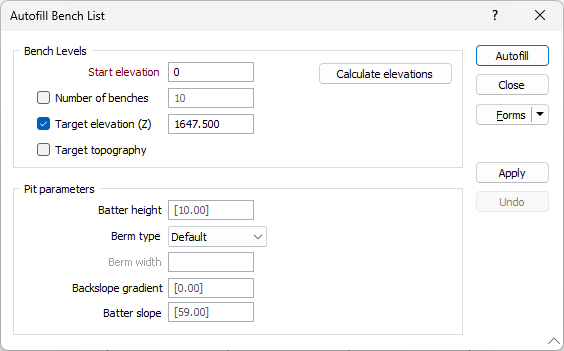
Bench Levels
The Bench Levels options determine the desired values of the output; including number of benches, elevation and topography.
Start elevation
Enter the elevation of the bottom string (toe) for the first bench in the pit projection. This value will be automatically calculated from the Wireframe input where selected.
The remaining benches, if any, will be auto-assigned the elevation based on the start. This value will be automatically populated when a Wireframe elevation wireframe has been specified.
Number of benches
Select this option to project the pit up or down by the required number of benches.
Target elevation (Z)
Select this option to project the pit up or down until it reaches a target elevation. This value is automatically calculated from the Wireframe input without any change to the Target Elevation check box.
Target Topography
Select this option to project the pit up or down until it fully penetrates the surface of the topography DTM configured in Setup.
Calculate Elevations
If you click the Calculate Elevations button at the right, a form is opened and you can calculate the elevation values for the bench list using a specified wireframe or block model.
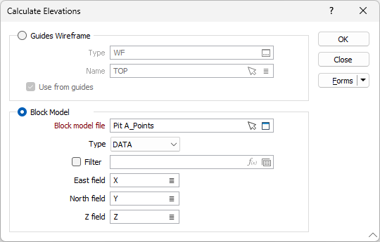
Guides wireframe
Select this option to specify a wireframe to use in calculating the elevation values for the benches.
Type, Name
Specify a Type and Name for the wireframe you want to use to calculate the benches. You can also use the Pick from Vizex button (or select the context menu option where available) to collapse the form and interactively select the required Wireframe to insert and return to the form.
Use from guides
Select the option to use the wireframes from any configured Guides for the pit design.
Note: This will disable any selected Guides Wireframe. Deselect the Use from guides option to specify a wireframe.
Block Model
Select this option to specify a block model to use in calculating the elevation values for the benches.
File
Enter (or double-click to select) the Block Model file. The default file Type for Block model data is DAT. You can also click the Pick from Vizex button to collapse the form and interactively select a layer containing the file to be inserted and return to the form.
Optionally, select or create a Filter to limit the data that is processed.
Easting, Northing, Z
Specify the names of the X, Y and Z coordinate fields in the Block Model file.
OK
Click OK to apply the elevation calculations as configured.
Pit Parameters
Batter height
After the initial cut the Bench will present a face, and at this stage a bench can also be called a Batter.
Batter height is the vertical distance between Toe and Crest of the bench or the vertical distance between the upper surface of the bench and the lower (floor) surface of the bench. It is the Batters that form the final pit limits.
A "bench', on the other hand, is an operational open-pit concept. Pits are mined by benches, this is the unit of reference for extraction. A bench has an upper and lower surface. It can be described as a tabular body with a specific thickness called Bench Height. When benches achieve the final pit limit they form a pit 'batter'.
Berm Type
The berm type for the bench - Default, Catch, Custom or None. The Berm type can be viewed and edited in the Data Properties for the bench.
The Custom berm type allows you to change the Berm Width for the berm from the default value to a custom solid value. Changing the Width of a berm will automatically set the Berm Type to Custom.
If no value is set for Width, then the Berm Type will be Default and the default width will apply. Setting the Berm Type to Default or Catch will change the width to the default value.
Berm width
The Berm width is the horizontal distance between a toe and a corresponding crest at the same level.
Berm Width is used to define the required width between bench faces. It is the measurement from the toe of the upper bench to the Crest of the lower Bench. Berms are necessary to provide slope stability and other safety reasons.
Backslope Gradient
Sometimes a slope may need to be designed into the berms in order to collect water or stone fragments against the pit wall.
Enter a Backslope Gradient value. The value you enter should fall between 1% and 30% (typically 5 or 10) %.
If your configured gradient unit is not percent, the value you enter will be capped to the values converted into those units that are equal to 1%-30%.
The Backslope Gradient value can be modified in the Data Properties for the bench.
Batter slope
The Batter slope is the default angle, measured from the horizontal, between successive toe and crest strings. The angle is measured in degrees to 2 decimal places and the angle value should be greater than 0 and less than 90.
The Apply button on the right-hand side of the form will quickly visualise your settings without leaving the form. You can preview the settings you have configured and, if required, make changes before finalising.
The Undo button at the right will revert any changes applied to the Bench Levels using the Apply button. Undo is only activated when Apply has been used.
When the details for the bench list have been configured in the Auto Bench List form, click the Autofill button to populate the Bench Levels grid.
Bench Pattern
To assign a bench pattern to the Bench Levels grid, you can click the Assign button in the toolbar to open the Bench Pattern form:
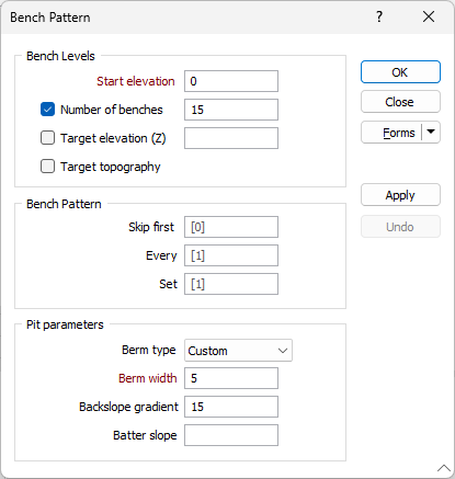
Bench Levels
The Bench Levels options determine the desired values of the output; including number of benches, elevation and topography.
Start elevation
Enter the Start elevation of the bottom string (toe) for the first bench in the pit projection. The remaining benches, if any, will be auto-assigned the elevation based on the start.
Number of benches
Select this option to project the pit up or down by the required number of benches.
Target elevation (Z)
Select this option to project the pit up or down until it reaches a target elevation.
Target Topography
Select this option to project the pit up or down until it fully penetrates the surface of the topography DTM configured in Setup.
Bench Pattern
Use the Bench Pattern options to configure the pattern for bench creation.
Skip First
Enter the number of benches to be missed at the beginning of the generated pattern. The default value is 0, which will skip no bench before creating the pattern.
Every
Enter the number of benches to be created per generated bench for the pattern. The default value is 1, which will create a bench pattern with no missed benches. If you enter a higher number, that number of benches will be missed before one is created in the pattern.
Set
Enter the total number of benches to be generated for the bench list pattern.
Pit Parameters
The Pit Parameters options contain settings for the Berm type, width, gradient and slope.
Berm type
Select the berm type for which the bench pattern applies - Default, Catch, Custom or None.
Berm width
When the Berm type is set to Custom, the Berm width can be entered in the field provided.
Backslope gradient
Sometimes a slope may need to be designed into the berms in order to collect water or stone fragments against the pit wall.
Enter a Backslope Gradient value. The value you enter should fall between 1% and 30% (typically 5 or 10) %.
If your configured gradient unit is not percent, the value you enter will be capped to the values converted into those units that are equal to 1%-30%.
The Backslope Gradient value can be modified in the Properties for the bench.
The Apply button on the right-hand side of the form will quickly visualise your settings without leaving the form. You can preview the settings you have configured and, if required, make changes before finalising.
The Undo button at the right will revert any changes applied to the Bench Levels using the Apply button. Undo is only activated when Apply has been used.
New Pit Bench List
The Bench List dialog will also open when you create a new Pit Design; loaded with the required parameters from your design settings, but without any benches created:
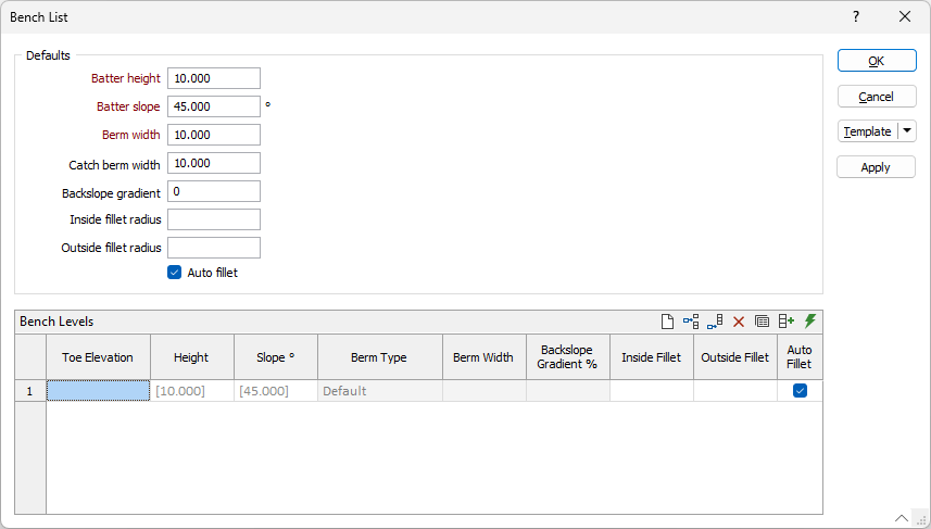
Benches can be created manually here, or using autofill as with the Bench List tool described above. If you use autofill, you will need to enter a Start elevation.
If you manually create the bench list, you will need to enter an elevation value in the first row. Benches with an undefined elevation in the first row when setting up a new design cannot be created. Any valid value entered in the first row will set each bench you add to the correct elevation according to the Height value. However, if no value is set for the first row, elevation values for subsequent benches will be blank, and therefore no benches will be displayed in the bench list.

If you create any base polygon at any level, it will appear with this elevation level in the Bench List.
The Apply button on the right-hand side of the form will quickly visualise your settings without leaving the form. You can preview the settings you have configured and, if required, make changes before finalising.
Template
The Template button is only available for Template Forms. Template Forms inherit saved or previously used values.
Click the Template button to select and open a saved form set template.
Load Template
Click the Load Template button to select and open a saved template to populate the fields of the form.
Save Template
Click the Save Template button to save the details of the current form as a template that can be loaded at a later time.
Manage
Click the Manage button to open the Template Forms manager which can be used to open, save, delete, import and export the template forms for your project.
Undo and Redo
Click Undo (CTRL + Z) to undo recent changes in the form. After an Undo, click Redo (CTRL + Y) to restore the last change that was undone.
Collapse
Collapse (roll-up) the form to preview a chart, or preview the results of an operation in Vizex, or obtain input values from Vizex, the Property Window, the File Editor, or the Plot Editor.