Display
Use the settings provided on the Display tab of the Block Model form to set the appearance of your block model.
Draw Style
Micromine Origin & Beyond block model draw styles fall into two groups.
The Optimised draw styles (listed above the divider in the Display Options form) are intended for modern hardware. They rely heavily on your computer's graphics card to display a block model, and achieve high performance by handing all of the rendering to the graphics processor.
The Legacy draw styles (below the divider) are retained for compatibility with existing form sets and older or less powerful computers.
The application may not be able to display a block model in the selected draw style on an inferior computer. In this situation it will fall back to progressively simpler draw styles until it finds one that the computer will handle. It may automatically choose a legacy draw style if it detects an older graphics card.
Optimised
Optimised draw styles all use OpenGL shaders to render the block model, and comprise:
| 3D Shaded | Displays the model as a 3D volume where the block faces appear as solids. |
| 3D Lines | Displays the model by only drawing the block edges. Equivalent to the old 3D Lines draw style with the same memory improvements as 3D Shaded. |
| 3D Points | Displays the model by drawing a point at the centroid of each block. Equivalent to the old 3D Points draw style, with improved memory use. |
| 2D Slice | Displays the model by drawing only those blocks intersected by the screen plane (in an orthogonal view) or three orthogonal planes that intersect at the camera viewpoint (rotated view). Although this is roughly equivalent to the old 2D Slice mode it has been extensively modernised and is capable of handling the largest models. This is the fall-back style for computers with inferior graphics cards. |
| To label one or more attributes of the block model in 2D Slice mode, use the check box options on the Label tab | |
| Auto | When the Auto option is selected, a 2D Slice draw style is applied when the current view is clipped. Otherwise, a 3D Shaded draw style is applied. |
Legacy
Legacy draw styles consist of:
| 3D Shell | (formerly 3D Shaded) Displays the blocks as if they were wireframes. On some older computers this style may provide better performance than the new 3D Shaded style. |
| 3D Frame | (formerly 3D Lines) Displays the blocks as if they were wireframes, using the Wireframe 3D Lines draw style. |
Hardware
The performance of the optimised draw styles depends very much on your graphics hardware and drivers, and it is vital that your hardware is appropriate for the volume of data with which you intend to work. We recommend that you use a high-end professional 3D graphics card for working with large models.
Although we cannot predict exactly how your computer will perform, with the right hardware and up-to-date graphics drivers it is possible to display very large block models (containing more than 100 million blocks) and still experience good real-time performance.
For the default method to be applied for the Shaded style, your graphics card must support OpenGL 3.2 as a minimum.
To view the details of your graphics configuration, including the OpenGL version:
-
Click the Project tab to open the backstage menu.
-
Select Options | Graphics.
Transparency
Use the transparency slider to specify the intensity of the display layer. The visibility of the layers underneath the current display layer will be determined by the degree of transparency you select.
Transparency is only available when the block model draw style is 2D Slice or 3D Frame.

Render with Scaled Block Dimensions
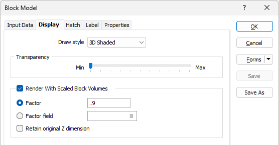
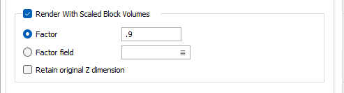
Select the Render with Scaled Block Dimensions check box option to configure the displayed dimensions of the blocks in the display.
Factor
If you prefer to display the blocks separated by a gap, then enter a Factor to determine the size of the displayed blocks.
Factor field
Variable block size factors can be applied to the model by specifying a Factor field. If the factor field's value is blank, then the block is NOT shown.
Retain original Z dimension
Select this check box to retain the original Z dimension when adjusting the block size.
A value of 0.5 will display the blocks half their actual size. Turn off the Render with Scaled Block Dimensions check box to display the true dimensions of each block.
Show Block Edges
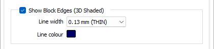
When 3D Shaded is the chosen draw style, select this option to draw lines between the blocks.
Line width and Line colour
Specify a line colour and a (THIN, MEDIUM, THICK, or custom) line width for the block edges. A large number of custom widths (in millimetres) are available for selection.
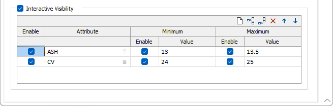
Interactive Block Visibility
The Interactive Block Visibility option makes it easy to show or hide blocks based on numeric values in the model. When this option is enabled, a histogram shows the distribution of those values; you then adjust the block visibility by moving sliders along the histogram.
This option is only enabled when you have selected a 3D Shaded, 3D Lines or 2D Slice draw style.
Enable
Enable the check boxes to show an attribute, and/or its minimum and maximum values, in the Interactive Visibility pane.
Attribute
Double-click (or click on the List icon) to select a field containing the values you will use to filter the display.
Minimum
Enter a Minimum cut-off value to limit the block display to those blocks with a value greater than the specified minimum.
Maximum
Enter a Maximum cut-off value to limit the block display to those blocks with a value less than the specified maximum.
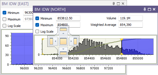
Each attribute is shown in a tabbed window of the pane:
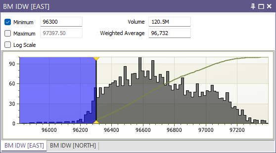
You can click and drag a tab to show the histogram for that attribute in a separate window: