

Clip by Plane
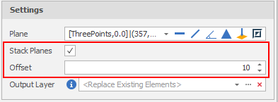
An Offset value can also be specified if you want to stack multiple planes.

Input Data
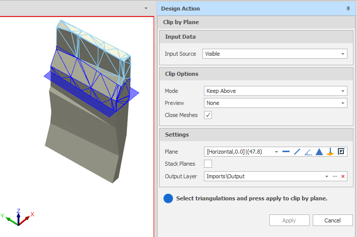
Select the Source of the data that will be used as input to the function:
| Selection | Design elements you have interactively selected in the Design Window. |
| Visible | Design elements that are visible in the loaded layer. Elements that have been specifically hidden are excluded. This a quick way of selecting all visible elements in a layer without having to explicitly select them. |
| Layer | One or more layers that you select. Names of layers currently loaded in the Design Window are shown in bold. |
For large datasets, you may prefer to select a layer rather than load that layer and select all of the elements in the layer. Selecting a non-applicable layer will have no effect. In most cases, an error icon  will indicate the chosen input layer is not valid. Hover over the icon to view a validation hint.
Clip Options
Mode
Select a (Keep Above, Keep Below, Keep Both) Clipping mode. This determines which triangulations are kept as a result of clipping by plane. The default mode is Keep Both.
Preview
Select a (None, Intersecting, All) Preview mode. This determines what kind of clipping preview is displayed.
| None | No Preview. |
| Intersecting | Display a clipped outline of the intersecting triangulations (Blue). |
| All | Display a clipped outline of the intersecting triangulations (as above) and also display an outline of the triangulations which will be kept but not clipped (Light Blue). |
Close Meshes
Select the Close Meshes check box if you want to close the clipped triangulations.
Settings
Plane
Use the tools to the right of the Plane drop-down to select a Plane Selection mode and define the plane:


 Horizontal
-
Click Horizontal on the plane selection toolbar.
-
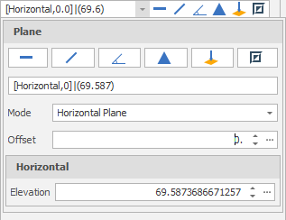
Digitise a point to set the elevation of a horizontal plane.
-
(Optional) Use the spin controls or enter a value to Offset the plane along the normal by a set amount. A negative offset value is allowed.
The point you have digitised are used to populate a Text Edit box at the top of the Plane Selection pane.
The Text Edit box can also be used to create or edit a plane from a string. The string format shows the plane selection mode and a zero or non-zero (if specified) offset value, followed by the elevation value.
 Vertical
-
Click Vertical on the plane selection toolbar.
-
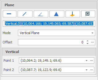
Digitise two points to define a vertical plane.
-
(Optional) Use the spin controls or enter a value to Offset the plane along the normal by a set amount. A negative offset value is allowed.
The points you have digitised are used to populate a Text Edit box at the top of the Plane Selection pane.
The Text Edit box can also be used to create a plane from a string. The string format shows the plane selection mode and a zero or non-zero (if specified) offset value, followed by the string format used for the conversion, which is “(x, y, z) | <a, b, c>“ where each lettered character can be a decimal number. (x, y, z) refers to the point of the plane. <a, b, c> refers to the vector normal of the plane.
 Slope
Slope
-
Click Slope on the plane selection toolbar.
-
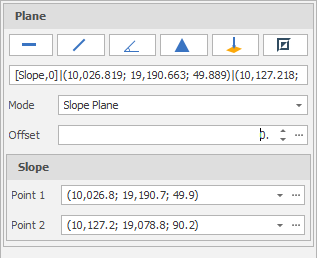
Digitise two points to define a slope plane.
-
(Optional) Use the spin controls or enter a value to Offset the plane along the normal by a set amount. A negative offset value is allowed.
The points you have digitised are used to populate a Text Edit box at the top of the Plane Selection pane.
The Text Edit box can also be used to create a plane from a string. The string format shows the plane selection mode and a zero or non-zero (if specified) offset value, followed by the string format used for the conversion, which is “(x, y, z) | <a, b, c>“ where each lettered character can be a decimal number. (x, y, z) refers to the point of the plane. <a, b, c> refers to the vector normal of the plane.
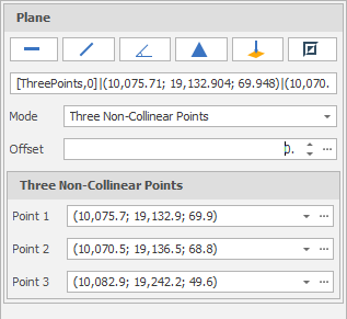
 Three Points
-
Click Three Points on the plane selection toolbar.
-
Digitise three non-collinear points to define a plane.
-
(Optional) Use the spin controls or enter a value to Offset the plane along the normal by a set amount. A negative offset value is allowed.
The points you have digitised are used to populate a Text Edit box at the top of the Plane Selection pane.
The Text Edit box can also be used to create a plane from a string. The string format shows the plane selection mode and a zero or non-zero (if specified) offset value, followed by the string format used for the conversion, which is “(x, y, z) | <a, b, c>“ where each lettered character can be a decimal number. (x, y, z) refers to the point of the plane. <a, b, c> refers to the vector normal of the plane.
 Points Normal
-
Click Point Normal on the plane selection toolbar.
-
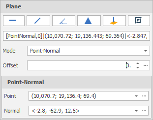
Digitise two points that define the origin and the normal of a plane.
-
(Optional) Use the spin controls or enter a value to Offset the plane along the normal by a set amount. A negative offset value is allowed.
The points you have digitised are used to populate a Text Edit box at the top of the Plane Selection pane.
The Text Edit box can also be used to create a plane from a string. The string format shows the plane selection mode and a zero or non-zero (if specified) offset value, followed by the string format used for the conversion, which is “(x, y, z) | <a, b, c>“ where each lettered character can be a decimal number. (x, y, z) refers to the point of the plane. <a, b, c> refers to the vector normal of the plane.
 Invert Plane
To invert the currently defined plane, click Invert Plane on the plane selection toolbar.
A vertical plane is inverted by swapping the two points and the mode does not change. When a horizonal or slope plane is inverted, the mode changes to Point-Normal. This is because a horizontal or slope plane always has a normal of <0,0,1>. The inverse is a normal of <0,0,-1> and this is only possible with a point normal plane definition.
Stack Planes
Select this check box to Stack multiple planes by specifying an Offset value:
Output Layer
Use the drop-down to select an Output Layer.
Tip: In the Layer Selection pane, you can right-click on the Layers node (or a folder) to Add a new layer.
If <No Layer Selected> then the Output triangulations will overwrite the triangulations in the Input layer.
Apply
Click Apply to clip the selected triangulations.
Check that the result of the operation is what you expect. If necessary, use CTRL+Z to undo.
Errors and Warnings
Errors are indicated by an icon to the left of the Text Edit box.
Horizontal, Vertical, Slope and Three Non-Collinear Points edits may result in the following errors:
-
‘Point cannot be null’
-
‘Point must be unique’
-
‘Points must be non-collinear’
Point-Normal (Point and Vector) edits may result in the following errors:
-
‘Point cannot be null’.
-
‘Vector cannot be null’
-
‘Vector must have a non-zero length’
A ‘Plane cannot be null’ error is shown when there are any other errors in the panel. A ‘Plane origin is outside data extents’ warning may also be shown.