

Intrusion

Input
Drillhole Database
Double-click (F3) to select
Optionally, select or create a filter to limit the data that is processed.
If you select the Filter check box, you can select an existing filter or create one using the Expression Editor by clicking the icon.
Interval file
Double-click (F3) to select an Interval file that contains the grades you want to interpolate. You can also click the Pick from Vizex button to collapse the form and interactively select a layer containing the file to be inserted and return to the form. You can optionally apply a Filter to the records in the file.
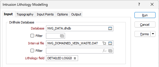
Lithology field
Double-click (F3) to select the name of a Character field that contains the lithology codes you want to include or exclude from the interpolation.
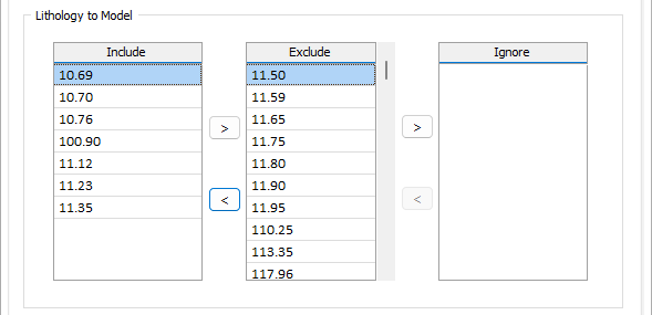
Lithology to Model
When you select a valid Lithology field, the Exclude grid is populated with a full list of Lithology codes. Use the arrows between the Include, Exclude and Ignore grids to select the codes you want to include, exclude and ignore.
The points for each of the Lithology codes in the Include and Exclude columns will be assigned a positive or negative value respectively. This value will be the distance from the closest 0 (boundary points).
For Included codes, the values will be positive. For Excluded codes, the values will be negative. Ignored codes are excluded altogether from the interpolation.
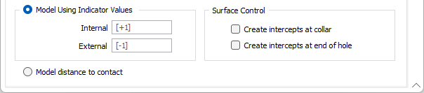
Model using Indicator values
Select this option to model the lithology using Internal and External indicator values.
Surface Control
To constrain the model to your drillholes, you can choose to create intercepts at the collar and at the end of each hole.
Create intercepts at collar
When this check box is selected, if an INCLUDED interval begins at the collar, a contact point will be created at the collar.
Create intercepts at end of hole
When this check box is selected, if an INCLUDED interval ends at the end of the hole, a contact point will be created at the end of the hole.
Note: In this context, 'end of hole' refers to the end of the deepest logged interval, and not necessarily the total depth of the hole.
Creating intercepts converts an open, extrapolated boundary into a hard-pinned contact point wherever the modelled unit is logged right at the collar (or right at the base of logging). This process can noticeably change the modelled surface and caution should be taken when using the options.
Model distance to contact
Select this option to model the distance to contact.
Note: To better utilise processor resources across multiple applications and tasks, when running computer-intensive operations it may be necessary to reduce the number of cores used by the application.
To modify the number of cores the application can use:
-
Click the Project tab to open the backstage menu.
- Click on the Resources tab of the Options | System | System Options form.