

DTM From Block Model

Input Block Model
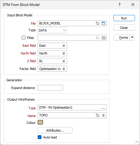
File
Select the file type and double-click to select the block model file from which you want to extract a DTM. You can also click the Pick from Vizex button to collapse the form and interactively select a layer containing the file to be inserted and return to the form.
Optionally, select or create a filter to limit the data that is processed.
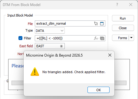
If you apply a filter which causes no triangles to be created, a warning message will be displayed:
East and North and Z fields
Specify the names of the fields in which Easting, Northing, and Z coordinates are stored in the block model file.
Factor field
Optionally select the field in the block model file in which the volumetric block factor for the regularised blocks is stored. If no value is provided, a factor of 1 for all blocks will be used, which will place the output points at the centre of the top face for the blocks.
Generation
Expand Distance
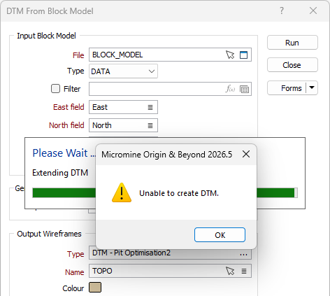
Optionally enter a value by which to extend the DTM extracted from the block model. By default, the value is 0.0. This will expand by the maximum half dimension size of the parent block; ensuring all blocks are encapsulated within the boundary of the DTM.
Note: If an especially high value is entered, the process may encounter an error and will not begin. An error message will be displayed:
Output Wireframes
Before you can generate wireframes and save them, you will need to specify their type and enter standard and (where appropriate) user-defined attributes for that type.
Double click (F3) or click the ellipsis in the Type field to select a wireframe type. To create a new wireframe type, press F5 or right-click and select New Type.
You can also use the Pick from Vizex button (or select the context menu option where available) to collapse the form and interactively select the required Wireframe to insert and return to the form.
Colour
Double click to select a default colour for the output wireframes.
Attributes
To manage User Defined Attributes for the selected wireframe type, click the Attributes button.
Auto load
Select this option to load the generated output in Vizex. The default draw style for an auto-loaded wireframe is 3D Shaded.
Forms
Click the Forms button to select and open a saved form set, or if a form set has been loaded, save the current form set.
Run
Finally, click Run to run the function.