

Triangulate Surface

Input
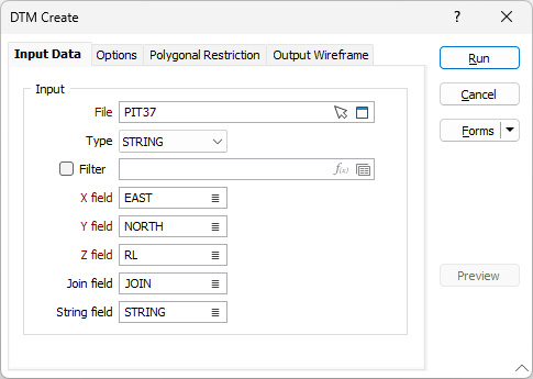
File
Enter the name and type of the Input file. This can be any file containing points with X, Y and Z coordinates. You can also click the Pick from Vizex button to collapse the form and interactively select a layer containing the file to be inserted and return to the form.
Optionally, select or create a filter to limit the data that is processed.
If you select the Filter check box, you can select an existing filter or create one using the Expression Editor by clicking the icon.
East and North and Z fields
Double-click to specify the names of the fields in which the Easting, Northing and Z coordinates are stored.
Join field
In forms that require polylines as an input, the values in this field define whether the data points in the input file should be joined by a line. If successive records have the same value in this field, a line will join the points. If two-factor topology is required, the values in a String field may also be used to segment the lines.
String field
In most forms, the String field is an optional generic attribute used to store a secondary input such as a code. Traditionally, this field has also been used with the Join field to define whether data points should be joined by a line, or strung, hence the name.
Forms
Click the Forms button to select and open a saved form set, or if a form set has been loaded, save the current form set.
Run
When you have set processing options, constraints, and output parameters, click Run to run the function.