Hole Options
On the Hole Options tab of the Drillhole Pattern Setup form, you can define the Azimuth, Inclination, and Depth that will be applied to the holes.
Holes
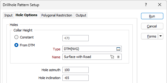
Collar Height
Specify whether the collar height values of the holes are constant or variable values obtained from a DTM. If you have chosen the Constant option, enter the collar height of the holes that will be created.
If you have chosen the From DTM option:
- Double-click or click on the Select icon to select a DTM Type.
- Double-click or click on the List icon to select the Name of the DTM.
You can also use the Pick from Vizex button (or select the context menu option where available) to collapse the form and interactively select the required Wireframe to insert and return to the form.
Use the fields provided to define the Azimuth and Inclination that will be applied to the holes.
The Hole azimuth is a bearing in degrees, measured from 0 for North and increasing clockwise. It will have no effect on a vertical hole (inclination of - 90).
The Hole inclination is the angle the hole makes with the azimuth, in the range 0 (horizontal) to - 90 (vertical). If no values are specified, a default inclination of -90 (vertical) and a default azimuth of zero are used.
Rate of Deviation
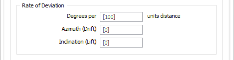
When you use the Create Pattern tool in the Drillhole | Planning tab, in the Planning group with a Planning layer open, the Rate of Deviation options are available.
The segments that you add will deviate in their orientation by a specified Azimuth deviation and Inclination deviation, measured in Degrees per units distance. Deviations are defined in terms of the drilling direction.
Degrees per
Enter a value in the field to define the distance to which the rate of deviation applies. The unit of distance, determined by the project settings, is displayed at the right of the field. When left blank, this value will use the Segment length.
Use the rate of deviation options with care. Drillhole deviation is the result of a complex interaction between the drilling parameters (bit type, feed pressure, rotation speed etc.), the cutting or hammering action of the bit, the rocks through which the hole passes, and the angle between the drill bit and the fabric of the country rock. Changing any one of these parameters may result in significantly different rates of deviation compared to other holes.
In a new project area, you should plan for straight holes until you have enough drilling to understand how the prior holes deviated. Even with this knowledge you should always consider any planned deviation to be an approximation of the completed drillhole.
Azimuth (Drift)
Enter the Azimith value which applies to the Drift for the rate of deviation.
Inclination (Lift)
Enter the Inclination value applicable to the Lift for the rate of deviation.
Drill To
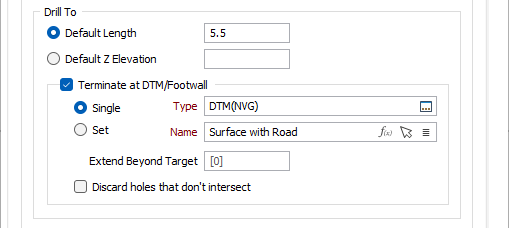
Select the relevant option and specify a Default Length or Default Z Elevation to 'drill to' for each hole in the pattern.
Select the Terminate at DTM/Footwall option if the drillholes should terminate at a selected DTM/Footwall or set. With the option selected, hole length will be determined by finding the intersection with the wireframe/wireframe set that gives the deepest hole. If no intersection can be made, then the default length or default Z elevation will be used for that hole.
If you have selected the Terminate at DTM/Footwall option, select whether you want to specify a Single DTM/Footwall or a Set.
Double-click or click on the Select icon to select a DTM/Footwall Type.
Double-click or click on the List icon to select the Name of the DTM/Footwall. You can also click the Pick from Vizex button to collapse the form and interactively select a layer containing the file to be inserted and return to the form.
If required, enter a measure for how far the drillhole length/elevation can Extend Beyond Target.
Select the Discard holes that don't intersect option to not include drillholes that do not intersect with the target wireframe in the Drillhole Pattern.
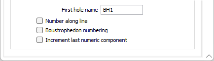
First hole name
Specify how the first hole name will be incremented in the direction of the bearing (the default) or along each line (when the Number along the line check box is selected). Boustrophedon numbering may also be applied. See: Numbering the holes
Increment last numeric component
Select this option to increment the last numeric component of a field when incrementing Character fields. For example, the Hole ID VS2012_001 will be incremented as VS2012_002.
If this option is not selected, the first (leftmost) numeric component of each field value will be incremented. For example, the Hole ID VS2012_001 will be incremented as VS2013_001.