

Grid to DTM

An option to sub-sample the grid before conversion is provided. This allows the 1, 2, 3, 4, 5th, etc point to be used.
Input
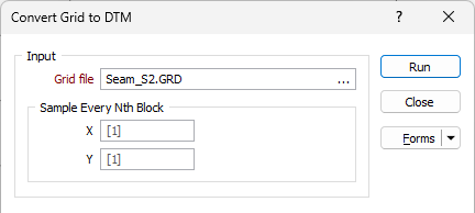
On the Input tab of the Grid to DTM form, double-click (F3) to select the name of the Grid file that will be converted to a DTM.
Sample every nth block
To sub-sample the grid before conversion, define the number of X and Y cells that will be used to create the X and Y range of the triangulated surface. Increasing the sampling interval will reduce the amount of memory required to generate a DTM. However, a simpler DTM will be produced as a result.
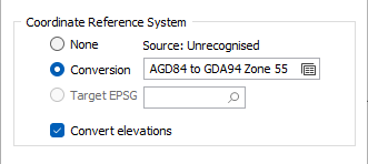
Coordinate Reference System
Modern geospatial data are defined in numerous coordinate systems from around the world, which can complicate the process of combining them into a single view. A typical example involves converting government data (in latitude/longitude coordinates) to the working coordinate system of your project; another is converting historic data on an old geodetic datum to a modern geocentric datum.
None
If you do not want to convert between coordinate systems as you import your spatial data, select None.
There are currently two conversion options:
Conversion
Select the Conversion option to select or create a new coordinate conversion form set to convert between coordinate systems. See: Coordinate System Conversion
Target EPSG
This option is only enabled if the Input file contains recognisable information about the coordinate system that it was registered in. The EPSG number and name of the source coordinate system are provided if they are recognised.
If the Target EPSG option is selected, then the
Convert Elevations
The Convert elevations option is selected by default. Z values will be converted using the transformation. You can (optionally) deselect it to prevent Z values being converted.
The Z direction field is optional in the Coordinate Conversion (File) tool because Z does not usually need to be converted. In some instances, conversion can also be unsuitable or incorrect. For this reason, the option is selected by default. Deselecting the Convert elevations option will result in the original Z values being kept unchanged.
Output
Type
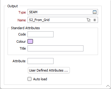
Select an output wireframe type. DTM is the default output type for this process.
Name
Enter (or click on the Select icon to select) the name of the DTM to be created. You can also use the Pick from Vizex button (or select the context menu option where available) to collapse the form and interactively select the required Wireframe to insert and return to the form.
Code
Optionally enter a code that can be used to differentiate between the different outputs generated as a result of the process.
Colour
Optionally double click (F3) to select a default display colour for the output DTM.
Title
Optionally enter a Title that is descriptive of the generated output.
Attributes
Click the Attributes button to set attributes for the DTM output.
User Defined Attributes may be mapped against the fields in the Input file. It is also possible to specify a default value for each attribute. Default values are used when a corresponding value in the Input file is either missing or is not mapped.
Auto load
Select this option to load the generated output in Vizex. The default Display setting for autoloaded wireframes is Auto, which will display the layers as 2D slices when Vizex is in clipped view.
Run
Finally, click Run to generate the Output DTM.