

Sidewall to Solid (form)
On ,the Mining | Underground Design tab, in the Wireframes group select Sidewall to Solid (form) to generate a solid from one or more polygonal (sidewall) shapes. You can define the length and the cross-sectional shape (profile) of the generated solid, and auto-load the result in Vizex.

For capped (semi-circular, circular, three-centred arch) profile shapes, the formation of the end of any working depends on the geometry of the sidewall string. If the end is a single segment, at near right angles to the sidewall, then the profile is extended all the way to the end, as shown in the following example:
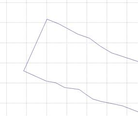
|
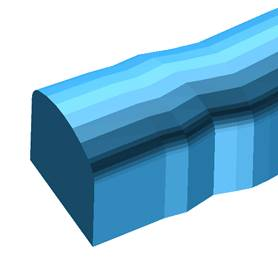
|
But if the end is not at near right angles to the sidewall, then the arch portion of the profile will be removed towards the end, as shown below:
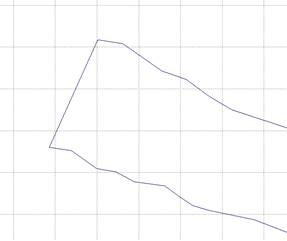
|
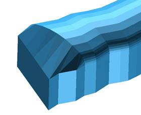
|
Input
File
On the Input tab of the form, select a file type and then double-click (F3) to select a file containing the sidewall polygons that will be used to generate solids. You can also click the Pick from Vizex button to collapse the form and interactively select a layer containing the file to be inserted and return to the form.
Optionally, select or create a filter to limit the data that is processed.
If you select the Filter check box, you can select an existing filter or create one using the Expression Editor by clicking the icon.
The strings in the Input file should be closed and have no self-intersections.
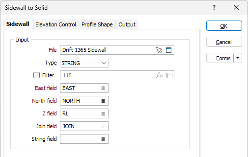
Easting and Northing and Z fields
Specify the names of the fields in which Easting, Northing, and Z coordinates are stored in the input file.
Join field
In forms that require polylines as an input, the values in this field define whether the data points in the input file should be joined by a line. If successive records have the same value in this field, a line will join the points. If two-factor topology is required, the values in a String field may also be used to segment the lines.
String field
In most forms, the String field is an optional generic attribute used to store a secondary input such as a code. Traditionally, this field has also been used with the Join field to define whether data points should be joined by a line, or strung, hence the name.
Projection Plane
The Projection Plane options are used to configure the working plane to suit the input data and allow modelling of the side walls with a given plane, or plane of best fit.
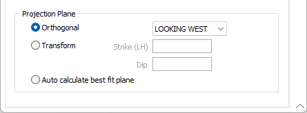
In the Projection Plane group, do one of the following:
- Select an Orthogonal plane definition
- Specify the parameters of a Transform plane definition
- Select an option to use the input point file extents to Auto calculate a plane of best fit
Orthogonal
Select the Orthogonal option to define an Orthogonal (LOOKING WEST, LOOKING NORTH, PLAN) projection plane.
Transform
Select the Transform option to define a transform projection plane.
Enter the Strike (LH) and Dip values that will be used to calculate the transformation. The Dip value entered must be a positive number.
Strike and dip notation is inconsistent and must include the handedness of the measurement to make it unambiguous. In this case, the handeness of the strike is assumed to be left-handed. A left-handed strike is one where the structure slopes downwards to the left when viewed along the direction of strike.
Auto calculate best fit plane from input
Select this option to use the extents of the input point file to calculate a plane of best fit.
Forms
Click the Forms button to select and open a saved form set, or if a form set has been loaded, save the current form set.
Manage
To save the types, attributes and names you have defined and re-use them in other functions, click the Manage button to create a form set or load an existing form set.
Save
Click Save to save your changes as the default form set.
Save As
Click Save As to save your changes as a new form set.
Reset
Click Reset to clear the form of all values and reset the form to its default state.
OK
Click the OK button to run the function and generate the solid.