

Hole Annotation
The extended hole annotation features described in this topic apply to most drillhole display functions. There are two ways of defining hole annotation: Default and Complex.
By default hole names are displayed at the top of the hole with the label running parallel to the uppermost segment of the trace. The application gets the hole annotation from the nominated Hole field in the Collar file.
When you select the Use complex parameters check box option to define complex hole annotation, you can control:
- What will be displayed - by specifying any of the field names in the collar file, that is, a field name other than the one containing the Hole identifier.
- How it will be coloured - by defining a colour set.
- The direction the text is facing and its size.
- The coordinates at the drillhole collar.
- The bottom of the hole annotation.
Hole annotation field
Double-click (or click on the Select icon) to select the name of the field containing the values that wil be used to annotate the collars. If this entry is left blank, the HOLE ID field will be used by default.
Colour set
The drillhole annotation can be colour coded. The type of colour coding will depend on the field type (C or N) of the hole annotation field. Double click (F3) to select the set that will be used to control the collar display colour. The colour set maps colours to text strings or numeric ranges. This determines the colour for each value in the colour field. Right click (F4) to create or edit a colour set.
Top/Bottom location
You can position the drillhole annotation at the top and bottom of the hole. The following options are provided:
NONE
No annotation will be displayed.
AUTO
The annotation will appear in the default position. This is parallel to the last segment in the drillhole trace.
CENTRE
The text of the drillhole annotation will appear at the top of the hole centred on the drillhole collar. It will be horizontal.
DIRECTION
The text of the drillhole annotation will be rotated about all drillhole collars and will depend on your entry in Top direction.
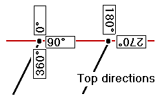
Top/Bottom direction
Enter the direction the top/bottom of hole text will face. 0° (default) displays the text vertically, with the baseline facing to the right. 90° displays the text in the normal page orientation. As you enter larger angles the text will continue to be rotated.
Label size factor
Enter the factor to control the size of labels. The default is 1.0. This factor will not change the size of the label on the display, however, it will be saved in the Plot file. When you create a plot, the label will be sized according to your entry.
Display collar coordinates
To display Coordinates annotation, choose CENTRE for the Top location and select the Display Collar coordinates check box option.
Enter the labels that will be appended to the Easting , Northing and Z coordinate values (e.g. E, N, Z). Put a space before the label if you do not want it to appear right up against the coordinate value.
Enter the number of Decimals that will be used when displaying the coordinate values.
If you want to suppress one of the coordinate values from the display enter an @ character in the appropriate field. For example, if you only want to display Easting and Northing coordinates, enter a @ in the Z response.
Bottom of hole
The parameters in the Bottom Of Hole group control the appearance of the Bottom of Hole annotation.
Your selection for Depth colour controls the colour in which the bottom of hole depth will appear (the value is taken from the Total Depth field in the Collar file). You can define the number of Decimals that will be used for the total depth value. If you specify more decimal places than are present in the Collar file, the value will be padded with zeros. The default for this field is 0 - no decimal places.
If you want to append text to the hole depth value, make an entry in the Annotation field (e.g. m, metres).
You can also control the Tick colour by double-clicking the Colour icon to make a colour selection.